

1. Overview
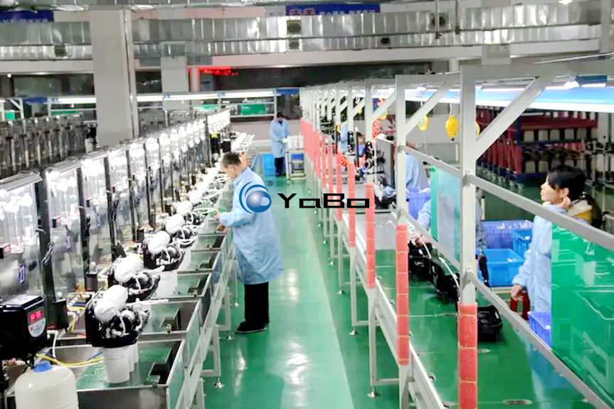
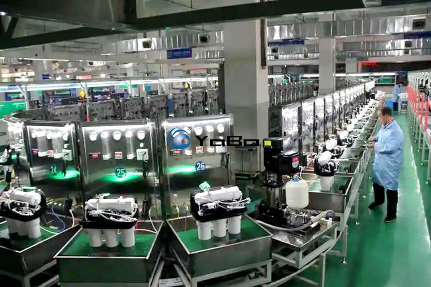
This RO water purifier assembly line is a standardized production system engineered specifically for Reverse Osmosis (RO) systems, Ultrafiltration (UF) units, and POU (Point-of-Use) dispensers. The system integrates a full production cycle, encompassing sub-assembly, final assembly, airtightness testing, performance validation, and final packaging. It is designed to address critical industry challenges such as low manual assembly efficiency, high risks of water leakage, and inconsistent quality control standards.
Adopting a flexible design philosophy, the line is customizable based on facility dimensions and production capacity requirements (ranging from 500 to 3,000 units per day). The process flow is segmented into distinct zones: Component Feeding & Pre-assembly, Main Unit Assembly, Performance Testing, Aesthetic Finishing & Packaging, and Finished Product Off-loading. The robust structure ensures stable operation, managed by a centralized PLC control system that enables synchronized line movement. The equipment supports mixed-model assembly and features reserved interfaces for MES (Manufacturing Execution Systems), allowing for real-time data acquisition of production metrics, test parameters, and machine status. This facilitates modern digital factory management and traceability. By optimizing workstation layout, the line minimizes material handling distances, reduces operator fatigue, and significantly enhances product consistency and yield rates.
2. Technical Specifications
2.1 Conveyor Structure & Transport System
The assembly line utilizes a dual-track accumulation chain conveyor system. The upper track facilitates product assembly and transfer, while the lower track handles pallet return, creating a closed-loop circulation. The accumulation chain mechanism employs 2.5x speed chains to drive the work pallets, ensuring stability during operation. Pallets are constructed from 2.5mm thick Anti-Static High-Density Polyethylene (HDPE). The frame is fabricated from 40mm×80mm high-quality carbon steel square tubing, treated with acid washing, phosphating, and electrostatic powder coating for corrosion and wear resistance.
Each workstation is equipped with pneumatic stopper cylinders and lift-and-locate mechanisms. Upon arrival at a designated station, sensors trigger the stopper to halt the pallet. Simultaneously, lift cylinders raise the pallet to ensure precise positioning for assembly tasks. Once operations are completed, the system automatically releases the pallet.
2.2 Modular Testing Station Technology
Performance testing is a critical phase of the production process. The line integrates multiple independent Comprehensive Testing Stations (typically 3–5 stations along the line), each comprising the following subsystems:
- Water Simulation System: Equipped with stainless steel tanks, multi-stage centrifugal pumps, and precision pressure regulators to simulate inlet pressures ranging from 0.1–0.8MPa. Quick-connect fittings accommodate various inlet diameters.
- Electrical Parameter Monitoring: High-precision digital power analyzers monitor input voltage, current, power consumption, and standby power to ensure compliance with electrical safety standards (e.g., IEC 60335-1 / GB 4706.1).
- Airtightness Detection System: Utilizing pneumatic boost pumps, the system performs high-pressure hold tests (0.6–1.0MPa) on welded joints and quick-connect fittings. Pressure transducers monitor pressure decay to automatically detect micro-leaks.
- Instrumentation & Display: Each station features shock-resistant analog pressure gauges or digital manometers to monitor inlet pressure, pre-RO membrane pressure, and drain ratios, providing operators with immediate visual feedback on filter installation and water flow status.
2.3 Ancillary Workstation Facilities
- ESD-Protected Workbenches: Ergonomic workbenches with ESD-safe green rubber mats are installed along the line. Steel shelving beneath the surface stores fasteners, filter housings, and components. Lockable drawers and cabinets are provided for tool storage and segregation of non-conforming items.
- Lighting & Power Infrastructure: Dual-row LED linear high-bay lights are mounted above the line, providing uniform illumination of 500–700 Lux. The line is wired with industrial-grade power outlets (220V/380V configurable) and a dedicated compressed air piping system, with quick-connect couplers at each station for pneumatic tools.
- Material Presentation System: Overhead multi-tiered shelving or gravity-fed flow racks are integrated above assembly stations. This ensures ergonomic access to components, minimizing operator reach and turn time, aligning with Lean Manufacturing principles.
2.4 Control System
The line is governed by a Siemens, Mitsubishi, or Omron PLC, interfaced via a Human-Machine Interface (HMI) touchscreen. The system supports both Automatic and Manual modes. In Automatic mode, the line runs at a preset pitch; Manual mode allows for individual station debugging. Safety features include overload protection, emergency stop circuits, and fault alarm diagnostics. In the event of a pallet jam or motor overload, the system halts immediately and displays the fault location. Variable Frequency Drives (VFDs) allow for infinite speed adjustment (0.5–5 m/min) to match varying operator proficiency levels.
3. Technical Parameters
(Note: The following parameters are standard reference values. Actual specifications will be customized based on specific process requirements and site conditions.)
| Category | Parameter | Specification |
|---|---|---|
| Conveyor System | Overall Length | 20m – 60m (Customizable in segments) |
| Effective Width | 600mm / 800mm / 1000mm | |
| Conveyor Type | 3x Accumulation Chain + Aluminum Alloy Guide Rails | |
| Pallet Size | 600×800mm / 800×1000mm (Customized to product) | |
| Line Speed | 0.5 – 5 m/min (VFD Controlled) | |
| Load Capacity | ≥ 50kg per station | |
| Electrical System | Control Voltage | DC 24V (Safety Control Circuit) |
| Power Supply | AC 380V, 3-Phase, 5-Wire, 50Hz | |
| Drive Motor | Branded Gear Reduction Motor, 0.75kW – 2.2kW | |
| Control System | PLC + HMI (Siemens / Mitsubishi / Omron Optional) | |
| Test Stations | Test Pressure Range | Water: 0-1.0MPa; Air: 0-1.2MPa |
| Test Items | Hydrostatic Pressure, Airtightness (Leak) Test, Flow Rate Test, Electrical Safety Test | |
| Dwell Time | 0-999s (HMI Adjustable) | |
| Sensor Accuracy | Pressure Transducers: Grade 0.5 | |
| Pneumatic System | Operating Pressure | 0.4 – 0.6 MPa |
| Air Consumption | Flow ≥ 300L/min (Customer Provided) | |
| Core Components | Stopper Cylinders, Lift Cylinders (Airtac / SMC Optional) | |
| Construction | Frame Material | 40×80mm Carbon Steel Square Tube, Powder Coated (RAL 7035) |
| Work Surface | 2mm Anti-Static Rubber Mat + 18mm MDF | |
| Finish Color | Computer Grey (RAL7035) or Custom | |
| Environment | Operating Conditions | Temp: -5℃ ~ +45℃, Humidity: 45% ~ 85% RH |
| Noise Level | ≤ 70dB (A) |
4. Application Value & Maintenance
By standardizing the production layout, this assembly line transforms discrete manual processes into a continuous, automated workflow. In practical operation, it mitigates quality variations caused by human error. Crucially, the standardized airtightness testing stations intercept potential leakage defects before products leave the factory, significantly reducing warranty claims. Routine maintenance focuses on chain lubrication, sensor cleaning, and drainage of pneumatic filters. It is recommended to inspect chain tension weekly and verify electrical terminal tightness monthly to ensure long-term operational stability and minimize the Total Cost of Ownership (TCO).